Silicon-Chip & Dick Smith Tic-Tac-Toe 2022 design challenge
George Galanis, 31 Jan 2022
For more information contact: Dr George Galanis
Background
This web page is actually a placeholder for articles about computational issues involved in human space travel. At the moment it contains an entry for the 2022 Dick Smith/Silicon-Chip Tic-Tac-Toe design challenge. Although the game of Tic-Tac-Toe might be a solved-problem, all the combinations of the game of Tic-Tac-Toe can easily be stored in a modern computer, Tic-Tac-Toe still provides an environment for trialling Artificial Intelligence (AI) concepts before moving onto more complex games and eventually application of AI techniques to real-world problems. The approach I took to the game of Tic-Tac-Toe is one based on human heuristics. I provide an example algorithm, written in Javascript, that implements the heuristics (that you can play against in the game above), as well as showing how you can turn that algorithm into logic circuits. So the three elements of providing a human like solution to Tic-Tac-Toe are here, that is: Heuristics, Algorithm, Logic, famously abbreviated as HAL in the 1968 movie 2001: A Space Odyssey.
The focus of the first part of the entry is on a design that does not include an integrated computational processor. This is in the spirit of the 1958 TicTacToe machine described in Dick Smith's autobiography My Adventurous life In his auto biography Dick Smith describes how taking on such a challenge can raise one's self esteem. In the spirit of that second aspect if this challenge extends beyond the 2022 call for entries the design for the Tic-Tac-Toe adjudicator system could be used in future challenges.
The design below outlines the adjudicator function that enforces the rules of play for Tic-Tac-Toe. The adjudicator system is based on TTL logic so that it is fast and electronically robust. An adjudicator could form the basis upon which future automated TicTacToe "machines" can be assessed for function and efficiency. The automated player at the top of this page is also described below. It is a Javascript simulation of a noughts and crosses machine. The design of the Javascript simulation is such that it could easily be ported to an Arduino, or similar microcontroller. It is also designed in such a way that it could be implemented in TTL without an integrated processor and interface to the Tic Tac Toe adjudicator.
Brief statement of System Requirements
The broad system requirements for Tic Tac Toe are relatively straight forward as the rules of the game are simple and well understood. A search through the internet reveals numerous designs and software approaches. Common approaches include table-lookup approaches, including using ROM for storing all possible board positions. Software solutions are commonly based on the minimax algorithm (as is typically found in modern game engines such as chess-engines). It may be possible for minimax solutions to be implemented without an integrated processor, but my assessment of such a solution is it would be large and expensive and probably best implemented using a microcontroller. So I limited my investigation to solutions specific to solving Tic-Tac-Toe rather than trying to implement a more general gaming engine approach. I also aimed at avoiding designs requiring storing all possible board states.
On the hardware side, not using integrated processors, the solutions I have seen appear to have two types of limitations. The first is that adjudicating the game is left as a future exercise. The machine may indicate that a win or draw has occurred but cannot not terminate the game. Such designs leave open the possibility that players may play out of turn, overwrite a square, or change a move after a game has finished. In the design here I have treated the adjudication of the game as an important requirement and the design includes a solution where the rules of the game are enforced. This ensures that a future automated player, or human player, could not win through an error or a cheat.
The second main aim for an adjudicator is to allow a variety of Tic-Tac-Toe machines to interface with it. If a TicTacToe adjudicator is available, future competitions could call for submissions of hardware that can interface with an adjudicator whose interface is published, or where the adjudicator hardware is readily available for use by the participants. Not only would this provide a standardised basis for actual hardware entries, but it would also reduce the work required by entrants designing and building entries and allow the entrants to focus on the automatic player (or other aspects of the game).
An additional requirement considered for the design is that the adjudicator should operate as fast as possible. The adjudicator should be able to keep up with entries that may want to demonstrate speed and efficiency. Given games would be played at high speed the adjudicator would have to reject illegal moves faster than they can be generated. Since a variety of Tic-Tac-Toe playing hardware could be plugged into an adjudicator the adjudicator needs to be as robust as possible.
With these aims and constraints in mind I decided that the adjudicator would be the prime focus of the system described below. The design uses common TTL components so that is as fast and electronically robust as possible. The design of a preliminary automated player could be implemented reasonably easily using an arduino or other microcontroller. A prototype of a recommended software solution can be found in the Javascript player at the top of this page. In addition, a brief outline of how the Javascript can be translated into TTL logic is included.
A TTL adjudicator design
Below is a logic diagram showing the all main components required for a TicTacToe adjudicator.
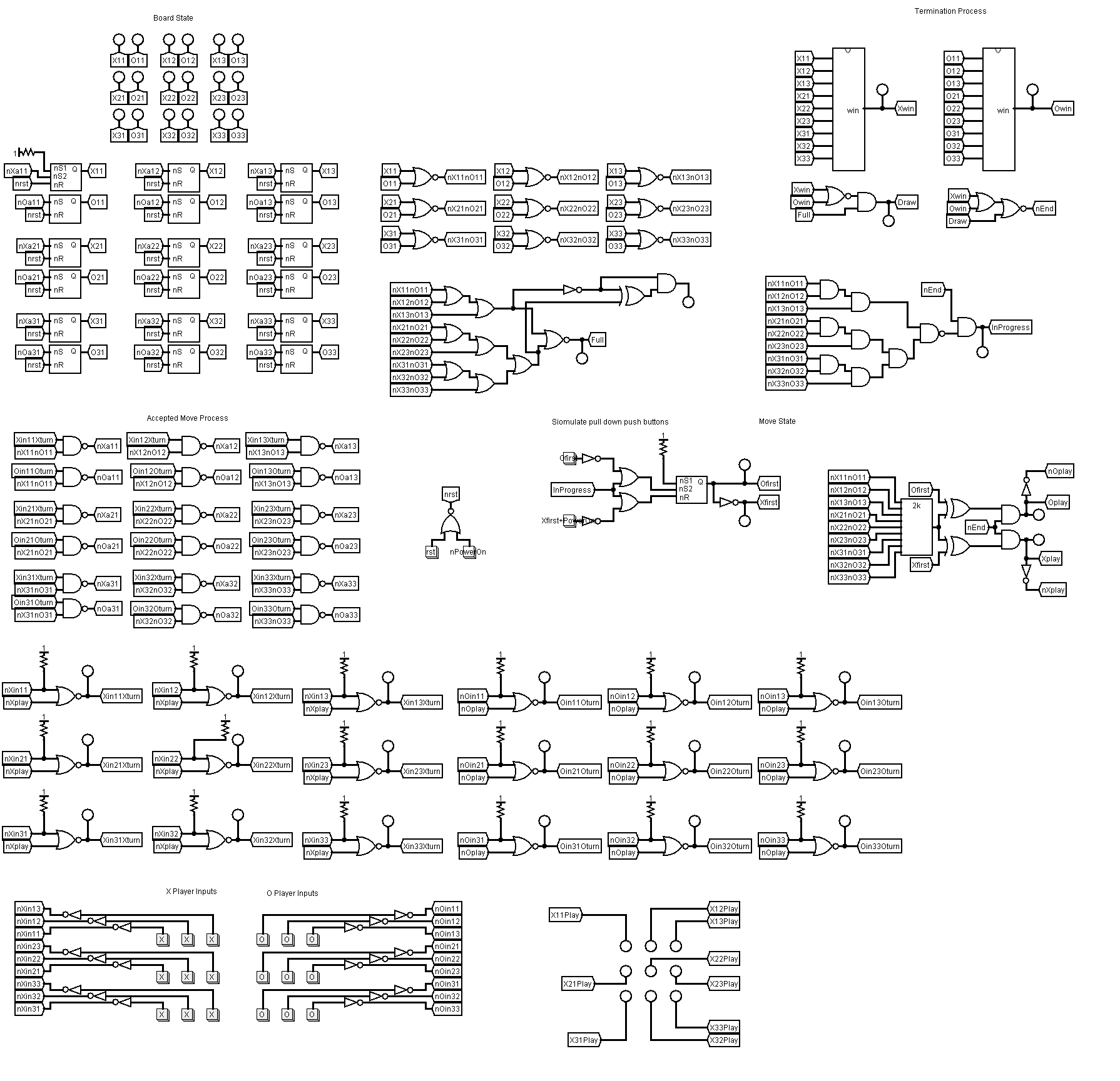
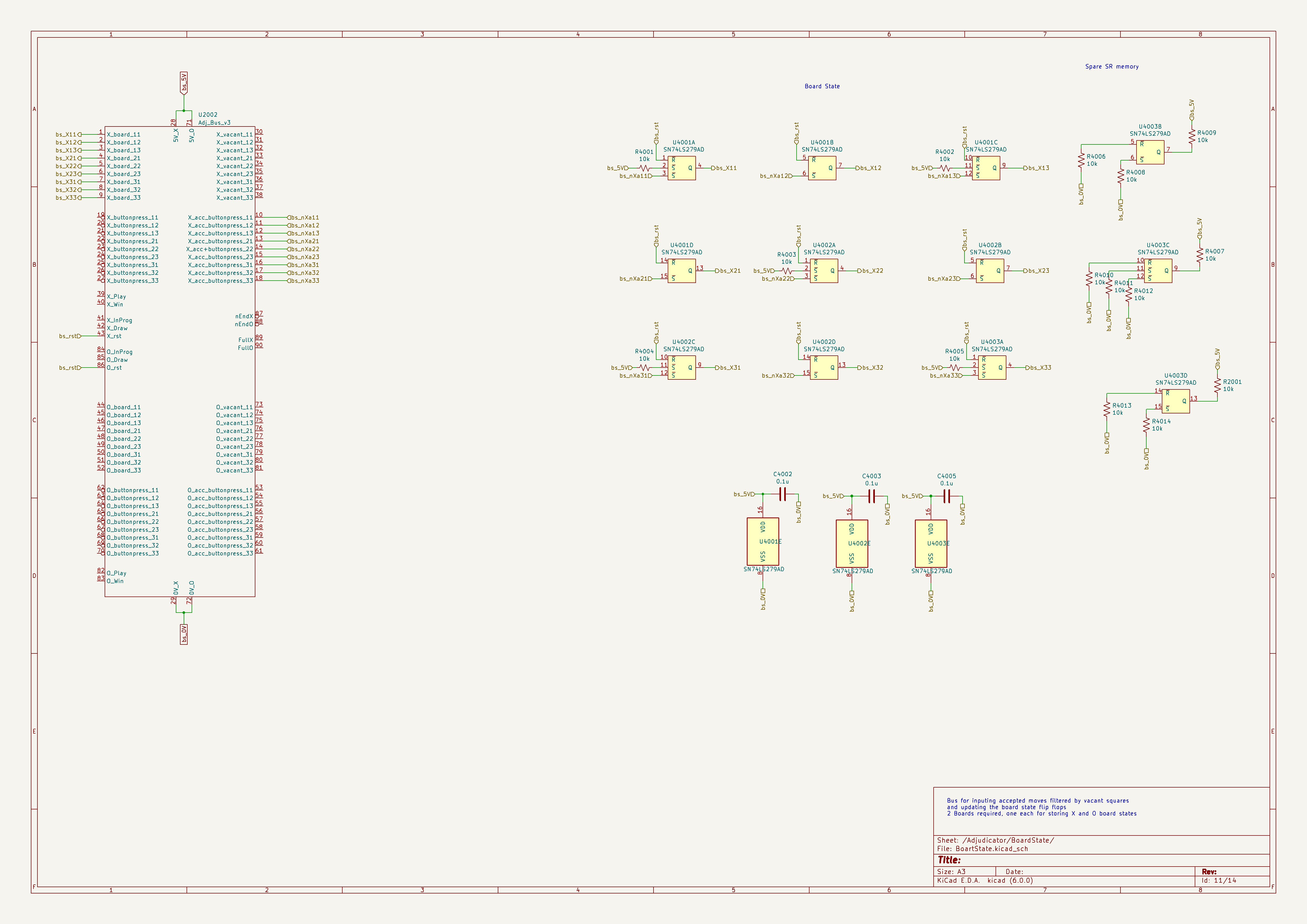
Central to this design are a set of 18 SR flip-flops that hold the state of the game board.
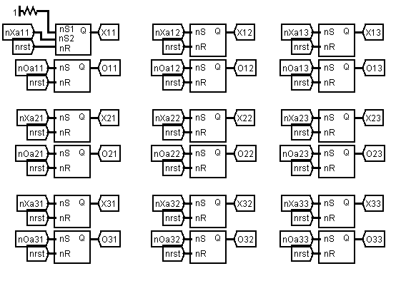
There are two flip-flops for each square of the board as each square can have three states, a cross, a nought or vacant. Hence two bits are required to hold the state of a square and therefore two flip-flops are required per square. The state of a flip-flop can be set by pulling the S pin to a logic low, and can be reset by pulling the R pin to a logic low. The output is available at the Q pin. The flip-flops can be reset by pulling the reset pin of the flip-flops low. The Tic-Tac-Toe board can be reset by pulling all the reset pins of all the flip-flops to low simultaneously.
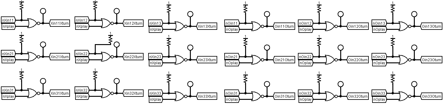
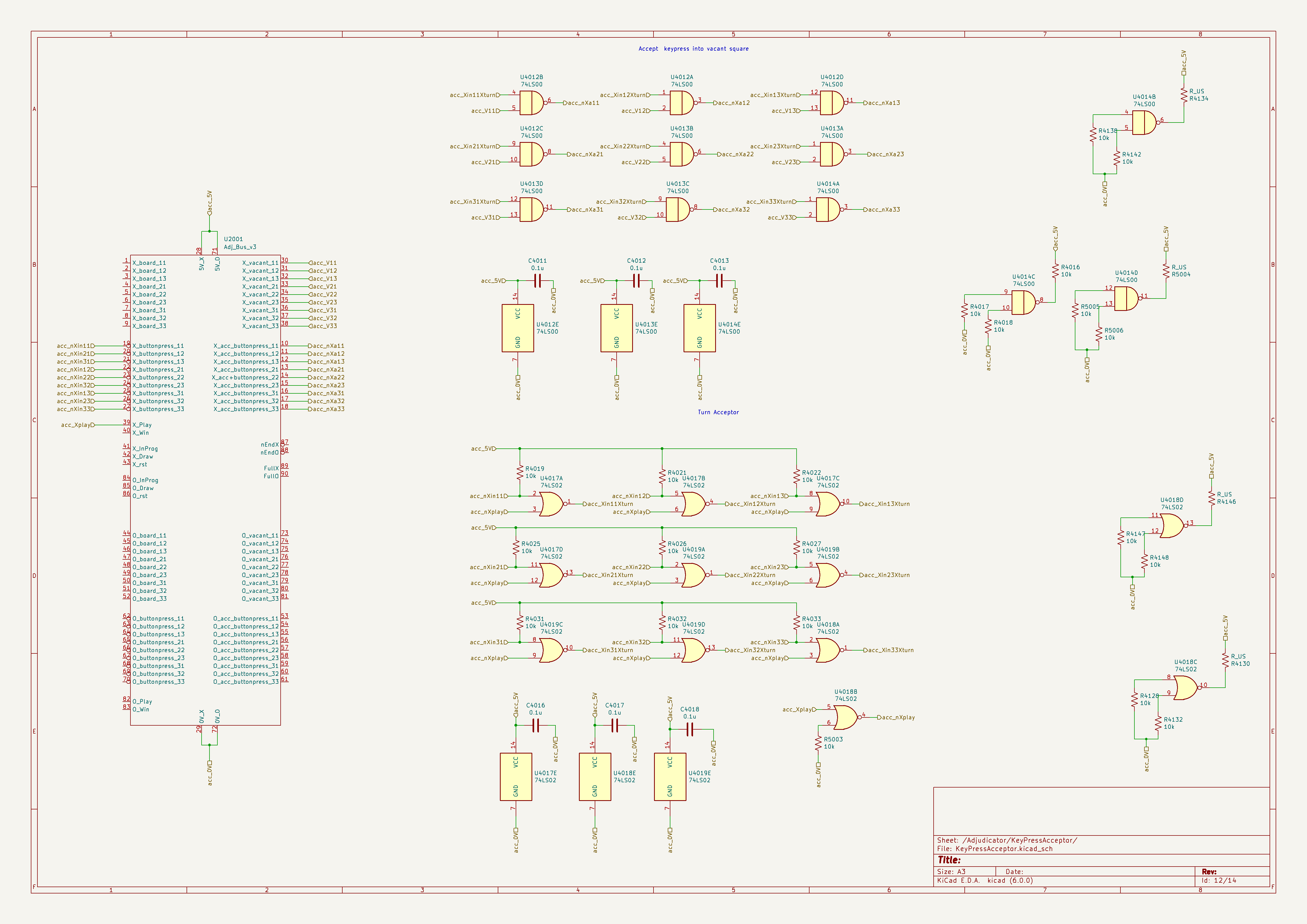
Moves are entered by players, human or automated, via a parrallel bus. A move can be entered for a square by momentarily pulling a nought or cross line low. The pulse then goes through two stages of acceptors. The first acceptor stage only accepts a move if it is the player's turn. This function is implemented with a set of NOR gates where the input to each flip-flop is "NOR"d with the player turn signal (described below).
The second filter only allows moves that are played into vacant squares.
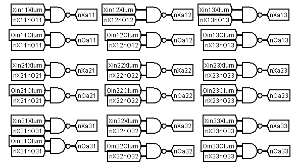
The vacant-square acceptor takes as input the board states of the flip-flops via logic that determines if a square is vacant (described later) Only if these two conditions are met will a move be accepted and stored in the respective flip-flop.
Note: this was the approach I took at the time I was designing this concept in December 2021. The logic diagram was developed using the logic simulation tool Logisim. That simulation tool uses mouse clicks for input and so you can only click one button at a time. I missed the possibility that a player can “cheat” by pressing more than one button at a time. This is highly unlikely to happen for human players because the TTL logic will accept the first keypress and then block the subsequent presses that occur just afterward because the logic for a vacant square will switch to containing a nought or cross and the logic for player turn will switch to the other player. However, an automated player could be designed to cheat using this loophole by pulling more than one input line low simultaneously. Given the modular nature of the adjudicator design it will be relatively straight forward to add another layer of logic to block out simultaneous key presses. This will be added in the next iteration of the design.
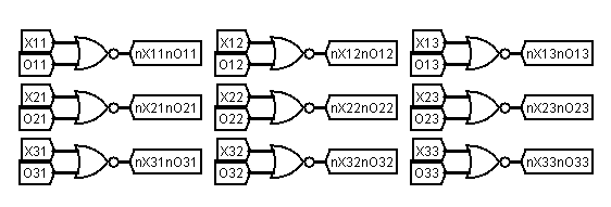
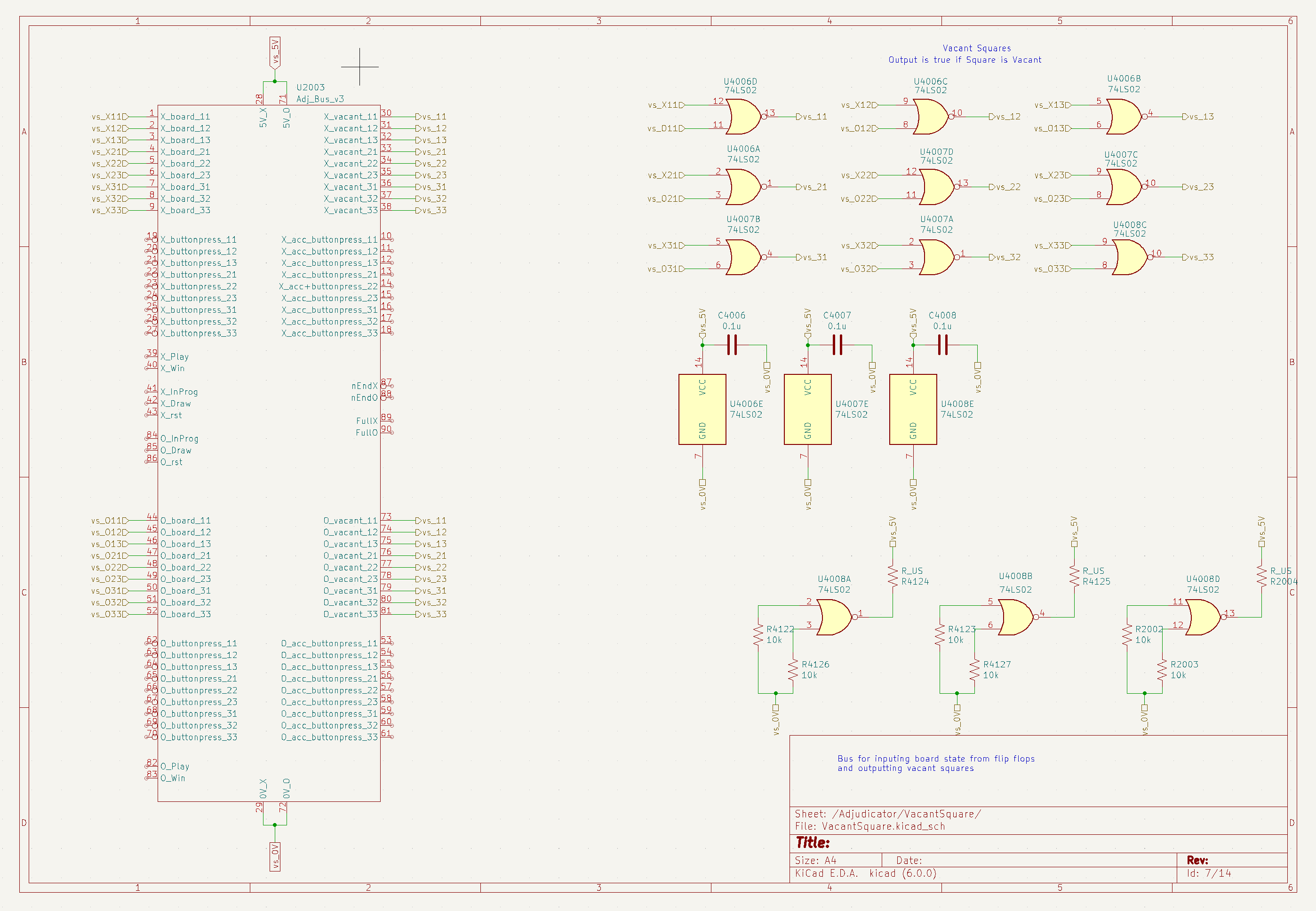
Once the adjudicator has accepted a button press into a flip-flop the output of the flip-flop propagates through the logic that derives the vacant state for each square. The output of the vacant square logic is labelled nX11nO11 etc., that is not X11 and not O11 is true for each vacant square (there is neither an X or O in square 11).
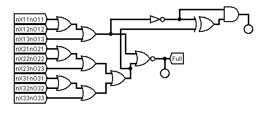
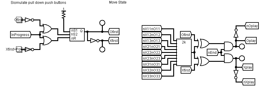
These vacant square values are used for the key acceptor as well as other parts of the adjudicator. For example the board is full when none of the squares are vacant, as shown below.
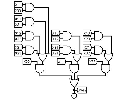
Another adjudicator logic function is detecting a win condition. There are two identical sub-circuits for the winner, one each for the nought or cross, the X winner circuit is shown below.
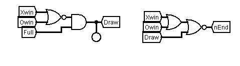
The output of the X and O win detectors are used in a logic circuit which determines Draw and then End-of-Game states.
The player turn is determined by a parity circuit, which uses the vacant squares and first-player state to determine which player's turn it is.
I have also included a multiplexer and demultiplexer to interface an Arduino or other microcontroller that has a limited number of pins for driving the input bus for the adjudicator.
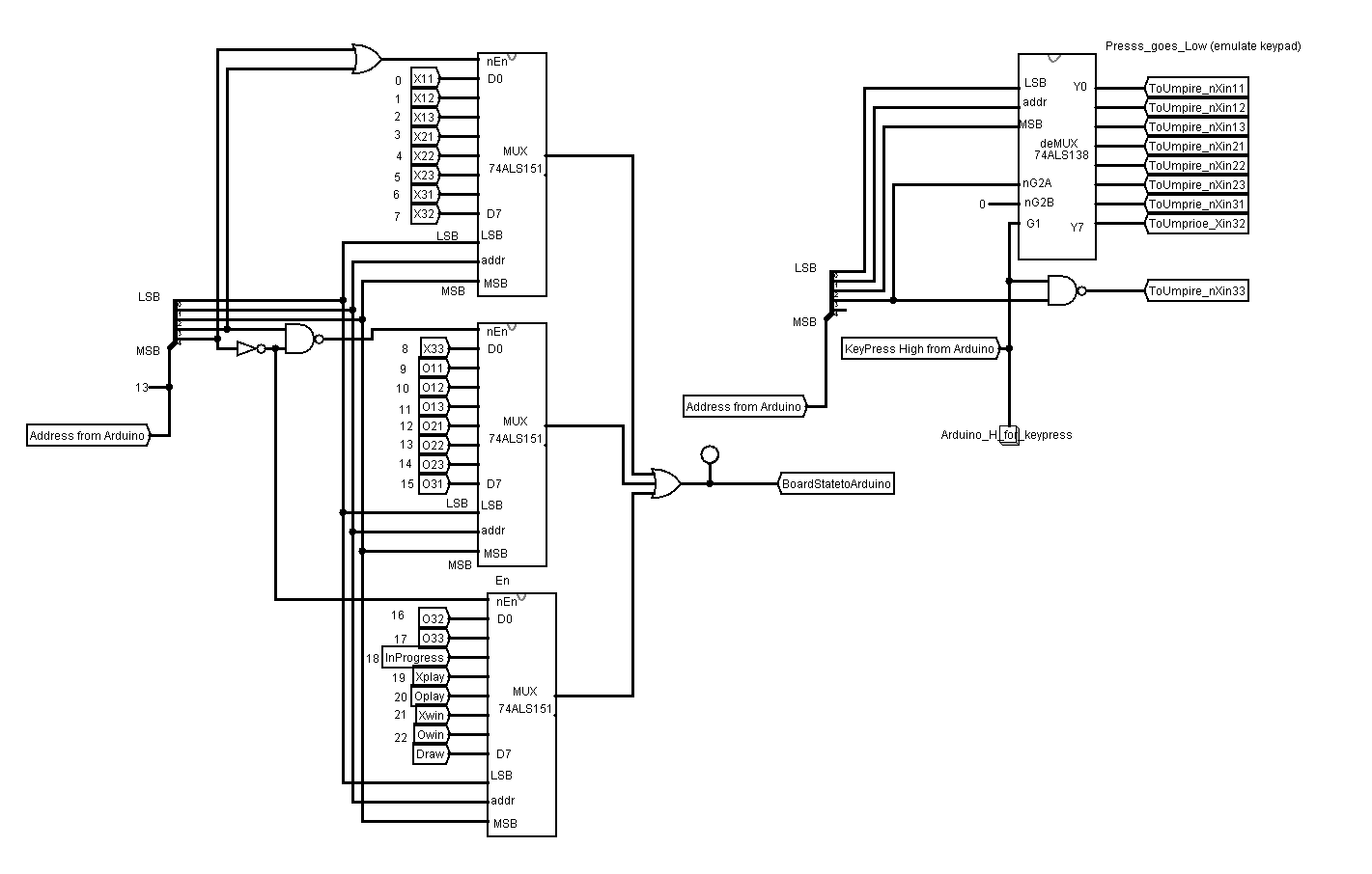
For the purposes of this description, I will assume it is an arduino connected to the adjudicator. The arduino sets the arduino pins connected to the MUX to create the address of the adjudicator pin it requires to be read. The value of that pin is then available at the output of the OR gate connected to the 3 multiplexer outputs. When the arduino wants to send a momentary button press to the adjudicator the arduino first sets the address of the square it wants to set. It then pulls the pin G1 of the deMux high to which the respective output pin of the deMux then drives the respective adjudicator pin.
This is a brief explanation of the adjudicator part of the Tic-Tac-Toe system. A logisim simulation of the Tic-Tac-Toe circuit is available from this website. The simulation runs in logisim version 2.7.1 and can be downloaded by following the link logisim I have attached the source code for logisim circuit file for this adjudicator here adjudicator_model. When you have downloaded the .circ source code copy it into a file with the suffix .circ and then open that file in the logisim program. Because of the way logisim operates you will have to press the reset button to initialise the flip-flops in the simulation. You will also have to select a player to enable the simulation to commence. In the schematics that follow I have included a circuit that will pull the reset pin to low on power up of the Tic-Tac-Toe adjudicator. That circuit will initialise the adjudicator squares to vacant as well as set the first player to crosses.
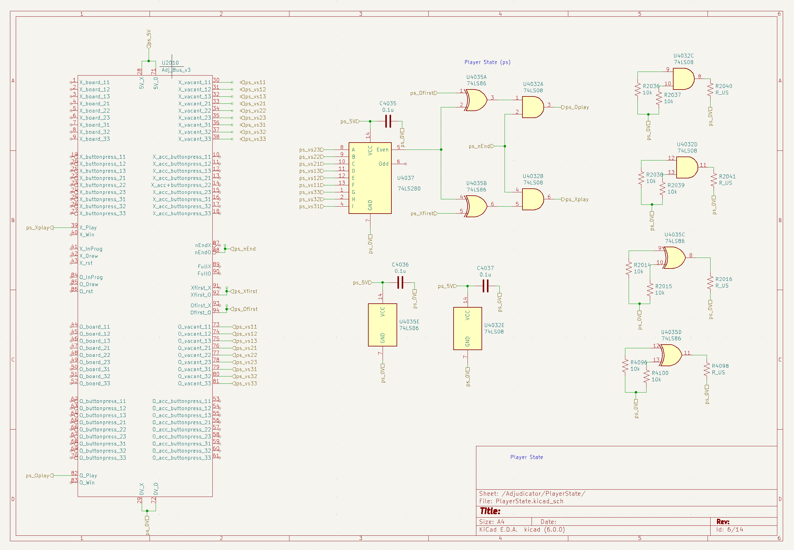
Schematics
The schematics below follow the logic diagrams from above. There is some additional circuitry included in the schematics. For example, I have included transistors for driving LEDs to get a bright output and not overload the outputs of the logic gates. I used a modular design for the adjudicator so that the complete adjudicator is made up of a set of 12 relatively simple modules. The modules can be stacked on top of each other using header pins and sockets on the bus pins. The first bus type is the full adjudicator bus which includes pins grouped into various sections, X state, O state, button press pins, vacant squares, etc. This bus is shown on the left of the schematic below.
The other bus is the player bus, which is a subset of the adjudicator bus with pins providing access for a single player. The full bus is not available to either player to ensure the players are restricted to play within the rules as set by the adjudicator. The player bus is shown in the schematic below and is at the bottom of the schematic.
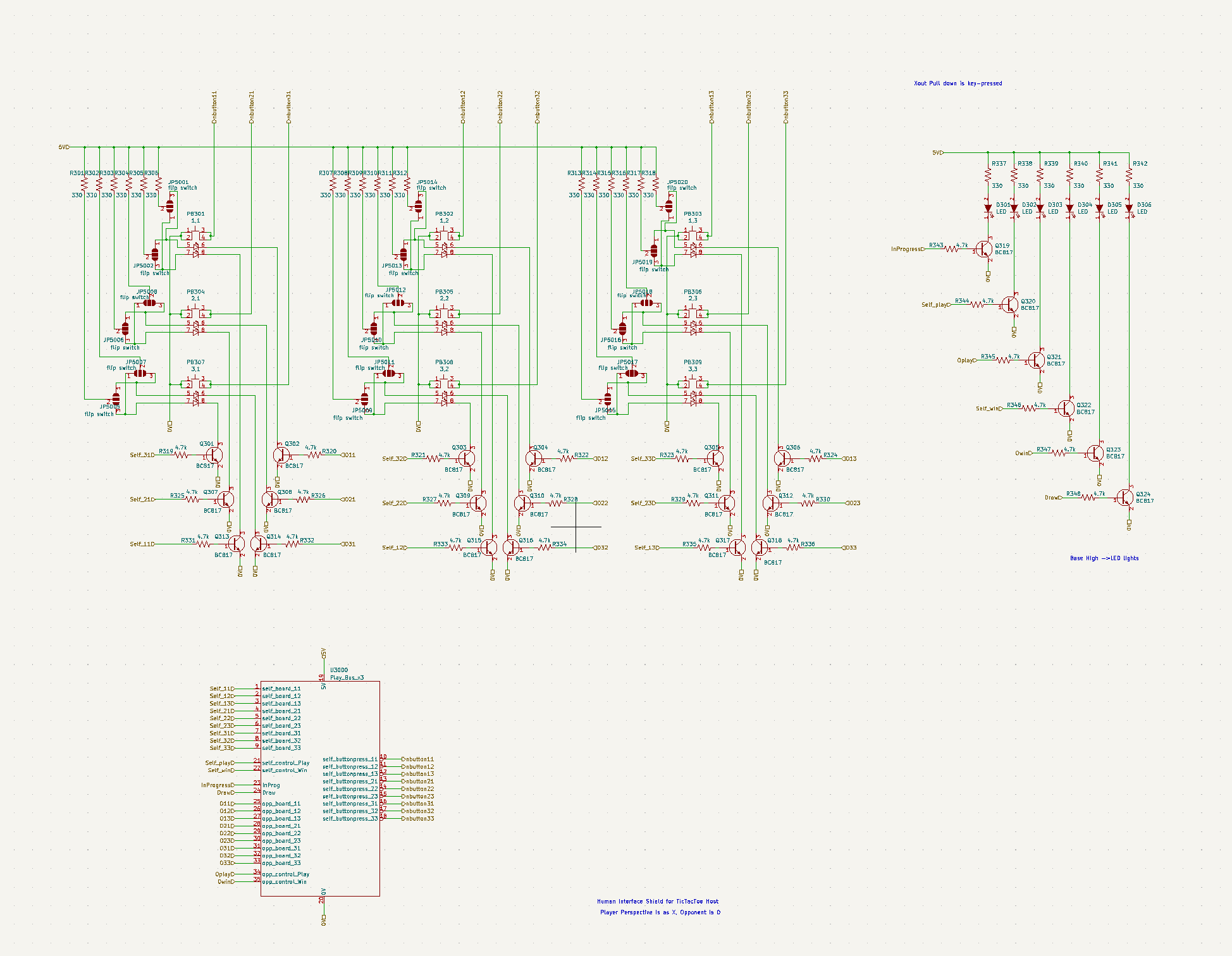
The schematic includes an interface for a human player, the HMI interface. This interface is made up of nine momentary push button switches for the player to enter a move, as well as transistors to drive the red and green LEDs in the push buttons as well as the leds than indicate the state of the game for providing feedback to the human player. The circuit for the HMI includes jumper pins that enable the push buttons to be installed on either side of the printed circuit board. This allows a single HMI PCB design to plug into the top and bottom of the adjudicator system. In that configuration, an adjudicator with two HMI modules on top and bottom, the system becomes a two human player TicTacToe game.
For human vs machine the arduino interface PCB could replace one of the human modules, and in future a TTL module could replace the arduino or human modules. In the PCB design section, further down the page, you can see the PCB layout uses 180 degree symmetry. This symmetry allows the same circuit design for players to be used to play nought or crosses. A similar concept applies for the win detection circuit of the adjudicator. The same win detector design can be used for both the nought and crosses players. Two win detectors are plugged into the adjudicator bus, but rotated through 180 degegrees so that each detector board operates on the pins for their respective player.
The following schematic shows the flip-flops that hold the board state.
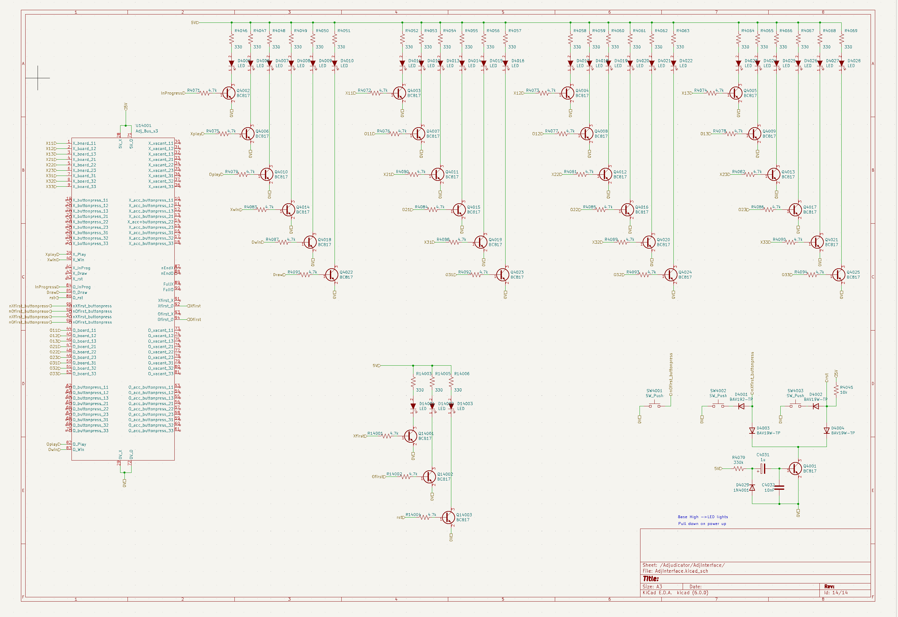
The schematic below shows the key acceptor circuits. All these logic circuits pretty much follow the logic circuits described earlier. Additional circuits in the schematic show the adjudicator bus as well as the power supply circuits, including pull up/down resistors for spare gates and bypass capacitors at the power supply pins of each 74LS IC. Unfortunately one of the compromises related to using a modular design is that there are unused logic gates that cannot be shared across modules. The 74LS ICs in the design are mostly quad gates and of course Tic-Tac-Toe has 9 squares, so there are always spare gates. Where additional gates are required for the mismatch between gates required and gates available in the ICs I have used an additional 74LS IC rather than attempting to make a single high quality gate out of discrete transistors. However, a more efficient approach will be investigated in a later iteration of this design, perhaps even going down the path of using gate-array chips. I have avoided gate-arrays in this design as that assumes advanced knowledge on the part of the readers, and the 74LS path is more in line with the spirit of the Dick Smith machine implemented with basic technology.
The vacant squares detector is shown in the schematic below.
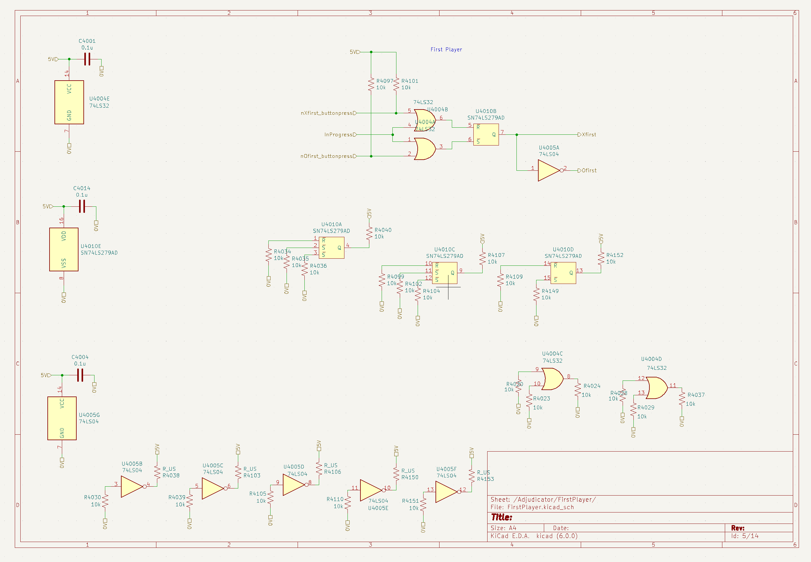
The First-player schematic is shown below. I was originally considering using a simple toggle switch for selecting players, but this design allows for the possibility of using a computer or microcontroller to control the adjudicator, so that games between two players can be played iteratively and the microcontroller recording the results.
The schematic for the player-state module is below. This module determines which player's turn it is.
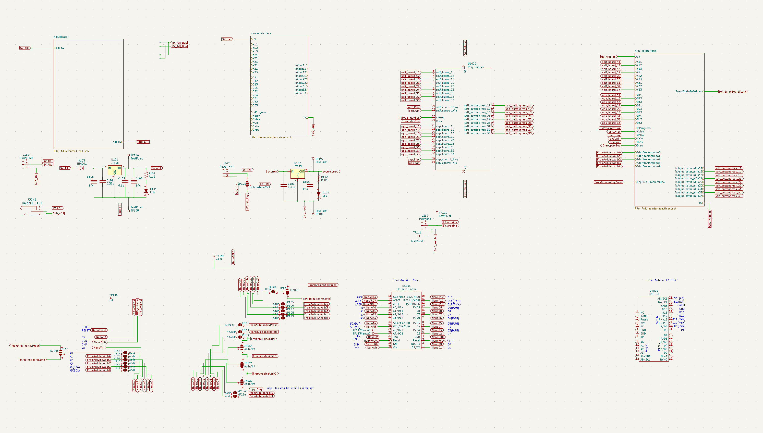
The schematic below shows the arduino nano interface module as well as the adjudicator and player busses and power supplies for adjudicator and HMI interface. I have included a second power regulator here as I did not want to risk the possibility that the HMI LEDs and arduino overload a single regulator. In later iterations one of the regulators could be left out or a single higher current regulator could be used instead of the basic 7805s I have used here.
I have included jumper pins for the Arduino Nano, so that some experimentation can be performed on which pins and ports are optimal for interacting with the adjudicator as well as experimenting with using the interrupt pins to improve Arduino performance. Later designs for the Arduino interface could be simplified if there is a clearly optimal pin arrangement.
Not shown here is an interface for the Arduino Uno R3 that is in development. The Arduino Uno is important as there are other manufacturers that use the Arduino Uno pin layout. For example STM32F334 Nucleo-64 boards use the Arduino standard for their boards. Inclusion of the Arduino Uno pin layout would be useful for anyone experimenting with these low cost but high performance microcontroller boards.
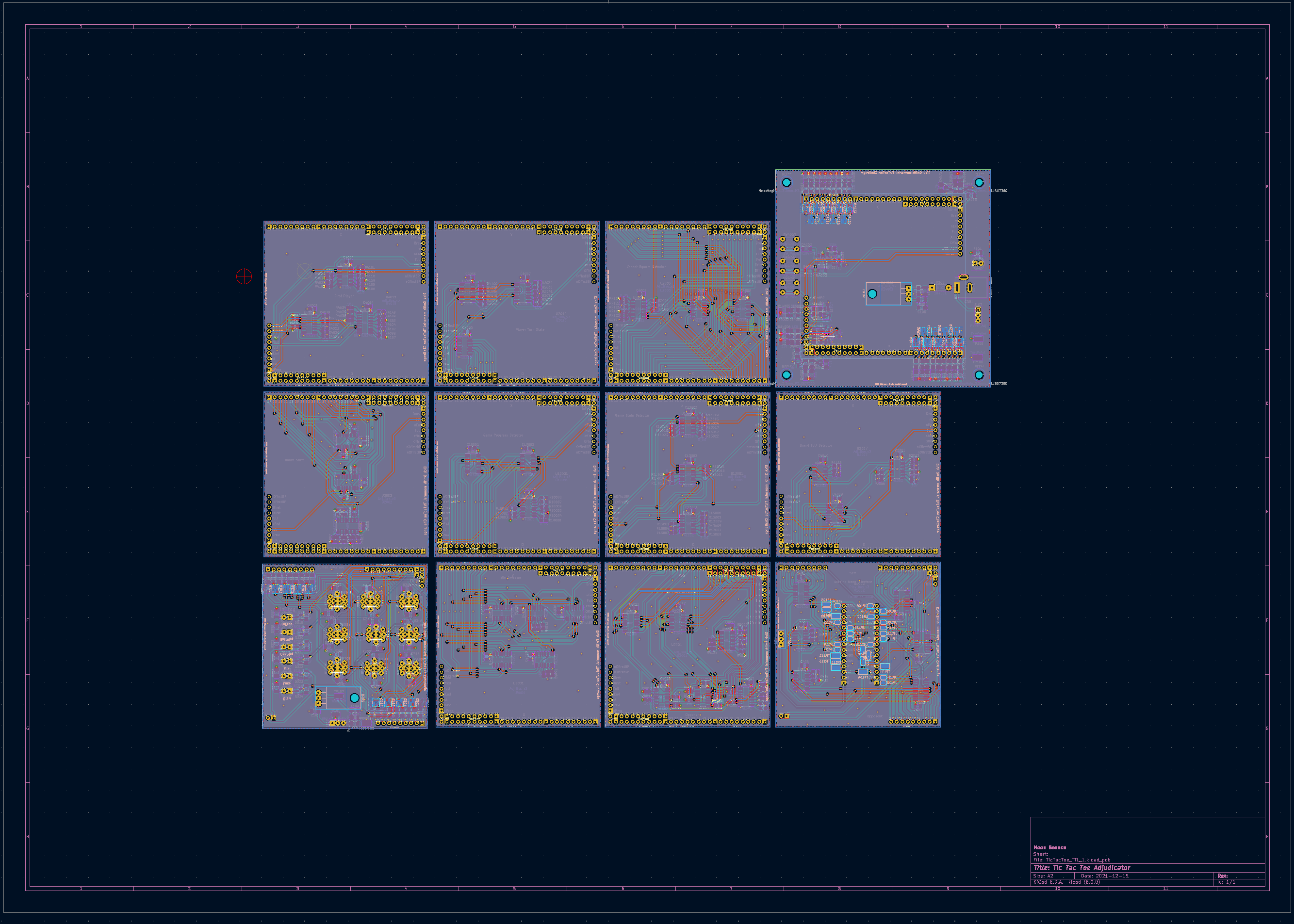
PCB designs
I have included a brief description of a suggested PCB layout here. The boards are four layer boards with power and ground on the two inner layers, and tracks for the digital signals on top and bottom layers. The PCB design is complete and is in a form that can be submitted to PCB manufacturers available on the internet. I also have a BOM ready to go with suppliers of components required for the adjudicator.
The PCB modules are designed to be slightly larger than an Arduino Uno. The main adjudicator board (the Adjudicator interface) is the largest of the PCBs so that it acts as the motherboard and holds the other boards as daughter boards as well as holding controls and digital state indicators on selected busses. One of the key considerations I had was that since the TicTacToe challenge is primarily an educational tool, it should display as much of the internal workings of the circuits as possible, hence I have included as many LEDs on the adjudicator as possible. A later iteration of design could include LEDs on other modules to facilitate even better indicators of the operation of the Tic-Tac-Toe adjudicator. Any additional probing required can of course be performed with simple TTL logic probes and low cost oscilloscopes.
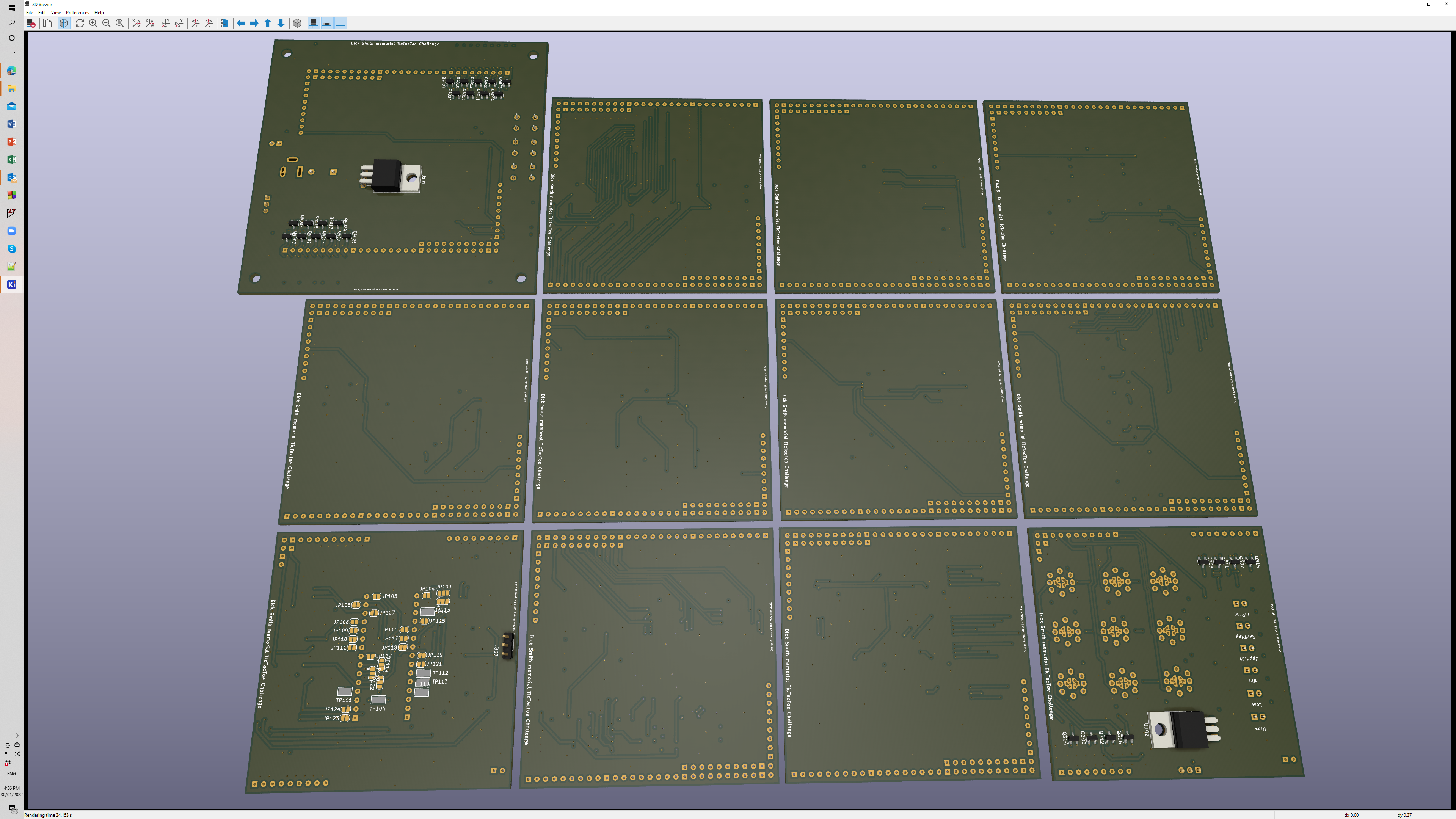
Below are 3D renderings of the adjudicator PCBs The renderings do not show all the components as development of 3D models for a number of components is still required. Header sockets for all the adjudicator buses are not shown on the renderings, but will be included in later iterations. However, the bus pins can be seen on the top and bottom of each PCB. The top of the PCBs is displayed below.
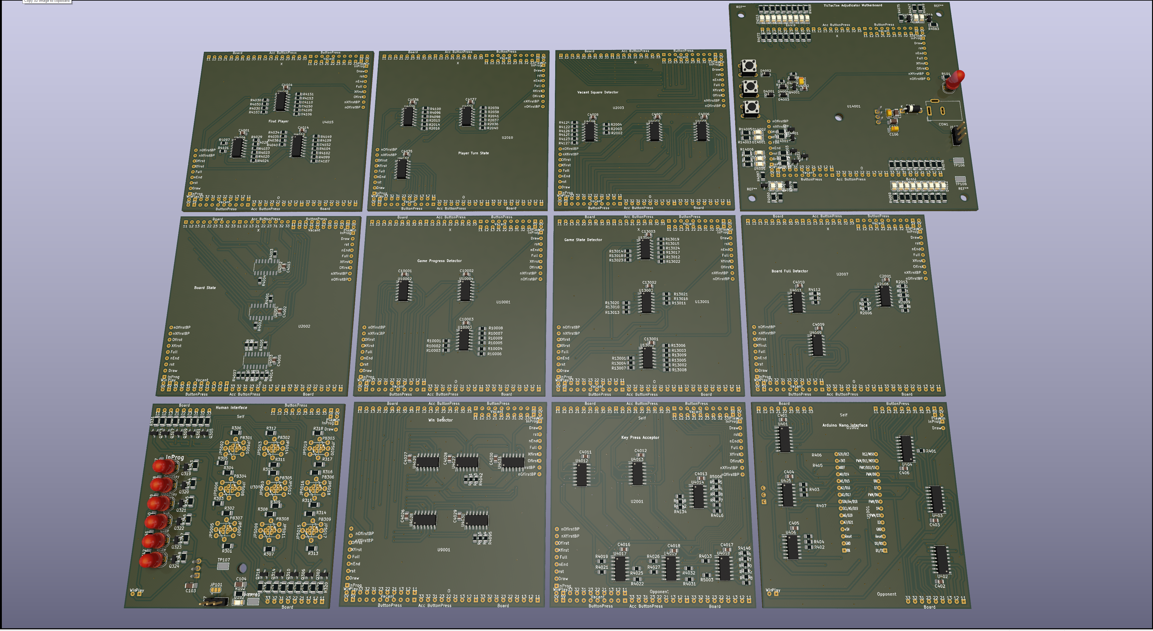
3D PCB bottom view shown below.
An automated Player, Or, How I stopped worrying and learned to love HAL
So far I have described the TicTacToe adjudicator. Here I describe an automated player and a simulation of the automated player can be found at the top of this page. The end-goal is to implement the automated player in TTL without an integrated processor. The design avoids synchronous processing but rather allow inputs to propagate through to outputs wherever possible.
An intermediate goal is to implement the automated player using an Arduino Nano, or perhaps the more powerful low cost Nucleo-64 boards from ST electronics.
The first step, implemented here on this page, is to simulate these systems using the Javascript language and the web browser as "the computer". The source-code for the simulation can be downloaded by following this link.
As it turns out the C++ language used for the Arduino is very similar to Javascript. As long as one avoids using Javascript specific features it is a fairly straight forward process to port code from Arduino to Javascript and vice-versa (and I have done this before several times). The other thing that simulating the Tic-Tac-Toe player using Javascript offers is debugging the algorithm that will eventually define the logic design required to play a game without an integrated processor.
So when I was developing the logic for the automated player in Javascript I restricted the logic at the core of the Tic-Tac-Toe player to "if then else" logic. To be clear as to how this translation from Javascript to TTL is possible consider the Javascript statement:
if (A && B){C=true}
This statement becomes the following logic circuit

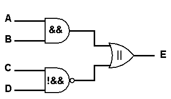
A more complicated Javascript statement such as:
if ((A && B) || !(C && D)) {E=true}
becomes the logic circuit:
The implication for this can be seen in the Javascript source code for the player simulation. For example opening the source code for the javascript simulator and inspecting the code in the function computerSecondMoveResponse (down in the second half of the source code listing) you will find the following code fragment:
if (bO[1][0] && (bX[0][1] || bX[0][2])) {computerSecondMove[0][0] = true}
if (bO[1][0] && (bX[2][1] || bX[2][2])) {computerSecondMove[2][0] = true}
if (bO[2][1] && (bX[1][0] || bX[0][0])) {computerSecondMove[2][0] = true}
if (bO[2][1] && (bX[1][2] || bX[0][2])) {computerSecondMove[2][2] = true}
This code fragment deals with the situation where the automated player is looking through the alternatives for a second move in response to an opening move. The first if statement, bO[1][0] is addressing the board (lower case "b") and the "O" (nought) flip-flop for the second row (Javascript arrays start at 0) and the first column. The second part of the if statement, bX[0][1], is looking at the X flip-flop in the first row and middle column. Similarly, after the || (Javascript for OR) the statement is looking at bX[0][2] which is the X flip-flop for first row and 3rd column. So if the "if" condition is satisfied the automated player will consider a good move to be to play a nought at [0][0] which is the top-left square. This if statement refers to the case where the opponent placed an X on an edge, and the automated player is looking for alternatives that will not lead to a loss. This single if statement is part of a rule-of-thumb, a heuristic. So the group of if statements shown in the code fragment are one part of a human like heuristic. For example the group of if statements in this area of code are essentially saying something like, if the self (the automated player) has played a nought on an edge, and the opponent has responded with an X in a corner where should the self play the next nought? In this automated player, the Javascript code defines all the heuristics the player will consider and the entirety of the heuristics makes up the algorithm. In the 1960s this interplay between Heuristics and ALgorithms was often referred to as Heuristic Algorithmic programming, HAL! The question I am exploring here is, is it possible to design the game playing logic this way? For Tic-Tac-Toe, the answer appears to be Yes. For games like chess this approach has fallen out of favour and for the last few decades chess engines typically use pruned brute force algorithms, like the minimax algorithm. More recently the company Deep Mind implemented deep-learning game engines to play Go and Chess. The deep-learning technique used simulations of neural networks, what might be considered the sub-atomic level of rules or heuristics. However, the HAL approach I have used here is still of interest for the simpler game of TicTacToe as it offers a way of implementing a much simpler TTL circuit for playing TicTacToe than would be possible if we tried to implement, say a minimax algorithm or deep learning algorithm.
This HAL approach to developing a Tic-Tac-Toe player leads to an intriguing game structure. The heuristics can be broken up into 3 distinct phases in the game. These are:
1. Opening (opening and response) As with other games, such as chess, the opening move does not force a win or prevent a loss (although in chess you have to be careful as you can lose by the 3rd or 4th move if you play the worst case against a perfect opponent). In Tic-Tac-Toe, the very first move can be a fixed move or preferably random move to be more challenging to an opponent. As the responder to the first move the situation is not trivial, because there are situations where an ideal player could force defeat if you play the wrong response to some opening moves, particularly corner openings. So the application of heuristics can be used to prevent a loss in the response. The code fragment in the description above describes what the implementation of such heuristics can look like.
2.Middle game. This is part of the game where forks and, what I have called "compound forks", lurk around in mysterious places. Heuristics are required to find the forks that can lead to a win, or use the fork heuristics in reverse to block a fork from the opponent. There are also compound forks where an attempt to block a fork creates the opportunity for the opponent to fork back on the next move. For example if the opponent has crosses in diagonally opposite corners and you have a nought in the middle, blocking the potential fork of crosses in the vacant corners only enables the opponent to play in the unblocked corner diagonally opposite. In this case the only alternative is not to block the fork but go for a counter-strike by placing a nought on an edge and threaten an immediate win on your next move. The heuristic for identifying compound forks requires not blocking but creating a counter threat. Human players use these type of heuristics in Chess as well. There is an old saying in Chess "the best defence is a counter offence". There are numerous heuristics that human players use in the middle game of Chess.
3. End game. The final phase of a game of Tic-Tac-Toe is where you look for a vacant square that simply gives you 3 across. If there is no such square then you must look for a square where the opponent can create 3 across and block it. Here you would need a circuit similar to the win detector to identify where there is a vacant square that will yield a win, or in reverse where the opponent has the opportunity to win and must be blocked.
The heuristics and algorithms for these phases can be found near the bottom of the Javascript source code, in the function called updateComputerAdviser and the functions called from that. The html interface in this Tic-Tac-Toe simulator indicates which heuristics are active when the automated player is making a move by colouring the automated player's noughts buttons. If you want to inspect the heuristics activated in different situations more closely there is an advisory mode available. In this mode the active heuristic is displayed until you manually select a move for the computer opponent. There is also a 2 player mode where you play both sides manually without any assistance from the automated player if you want to play in a 2 player mode.